
Tips and Hints for Completing a Successful Testing Job and How to Measure Concrete Thickness
Welcome to the new financial year for 2013, all of us at PCTE hope you had a fruitful business year.
 In this post we will be taking a fresh start and looking at some NDT questions people ask again and again, we will also talk about some hints and tips we have found working with the systems we supply that may not be obvious.
We are also presenting a slightly more in depth article on various means of measuring concrete slab thickness.
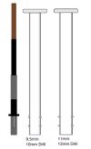
I would also like to draw attention to the upcoming changes in the North American standard for humidity testing, the update for ASTM2170-11 has changed how drilled in humidity probes must be placed, the image to the right shows the new format and anyone at PCTE would be happy to explain how these would affect humidity testing in your business.
NDT Basics and Hints
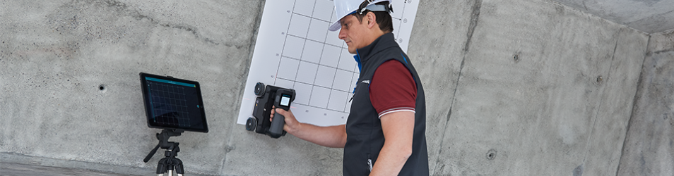
We write a lot about the technical aspects of our equipment; the physics behind the technique or the finer points of interpretation. For a review of this information you will find a technical rundown of each piece of equipment here. But what of the preparation and training? We have put together some salient points about what should be considered by practitioners before getting our equipment into the field.
Standards
We get asked a lot about standards to follow for NDTs such as Schmidt Hammers or Covermeters. Unfortunately there is no Australian Standard for these technologies. There was a Handbook written in 1984, “HB 34: Close to surface testing of Hardened Concrete”, however this was very basic and is now defunct. So when carrying our testing on site which standard should we follow? Sourcing standards from Europe, North America or even Asia are all options or various institutions often publish their own work methods, if a lot of the same test work is to be done you can even formulate a company standard. The important thing is to choose a standard or methodology with forethought and stick to it. Consider its efficacy as a professional. This provides consistency of measurement.
If you are a testing Contractor once your test standard is clearly set out you can also apply for NATA registration for undertaking those tests. Although this is not common it is an excellent way to demonstrate your credentials.
Training
There are generally no requirements for formal qualifications for carrying out NDT’s on concrete in Australia as too few people are NATA registered. Training however is highly advisable. A minimum would be to attain training from the supplier of the equipment. Institutions such as Engineers Australia, the Australasian Corrosion Association, the Australian Concrete Repair Association and the Concrete Institute of Australia all provide information about the available training courses in Australia or in fact provide their own. Seeking out training from organisations is highly advisable for anyone entering the industry or wanting to refresh their skills.
Project Preparation
A few things to keep in mind when preparing for an inspection are:
- Power and water- in shut downs it may be necessary to have a generator or water container
- Check the weather- power tools should never be used outside in any wet weather
- If the work is on a soffit do you have a ladder, scaffold or work platform that meets the site’s safety requirements? Remember you can only access about 1.5m x 1.5m from a ladder
- Chances are you’ll need whatever you leave behind. Listen to that little voice that tells you to take a second Covermeter even if you have the GPR system ready to go.
- Along the similar vein if you have two techniques that are possibly capable of performing the test but differently, take both machines. Even if they both work you will walk away much more confident in your results
- If you are unable to visit site prior to the job get as many photos as you can, don’t take your clients word that access is sufficient.
- If you believe that the technique being employed is of 50/50 chance of succeeding convince your customer to do a day trial. You may win more work and the chances of writing a disappointing report are diminished
- However you can plan as much as you like but you should always be flexible enough to throw out plan A when you arrive on site or after an hour. We always recommend customers re-assess after an hour to make sure they get the most out of their limited time onsite.
- While formal NDT equipment is often the best tool for the job there are a number of household and commercial items that can be useful during surveys as an adjunct to NDT tools.
Electrical Contact to Reinforcing
- Half-cell potential [HCP] testing with a Corromap or Canin is straightforward in theory. In practice one of the most difficult parts of the job is ensuring a solid reinforcing connection and in the case of the Canin ensuring continuity.
- A method commonly used during installation of corrosion monitoring probes that can be co-opted for HCP testing is drilling pilot holes and using self-tapping screws into the rebar as one solid way to ensure good contact. It is also good to have a range of alligator clips, locking clamps and plyers on hand and plenty of cable.
Ground Truthing for accurate Thickness
- As discussed below a number of tests such as ground penetrating radar and Impact echo testing can be used to determine slab thickness. The measurements are reasonably accurate but rely upon an assumed speed of radar or sound propagation through concrete to calculate their measurements. A single accurate measurement taken at the edge of a slab or wall, or even with the aid of a small diameter pilot hole drilled and measured, can greatly increase the accuracy of either testing method.
Quantifying Visual Inspection
Visual inspection will usually involve a survey of cracks and other flaws, measuring cracks with normal measuring devices can be tricky, crack width meters or magnifiers with measuring scales such as offered in our crack measuring range make this task simpler and can often be photographed to provide evidence of the actual crack state for reports. If required crack monitors can be glued either side of the crack and any motion or changes detected.
Summary of Element Thickness Measurement
Traditionally, destructive methods such as coring are used for the assessment of concrete thickness of an existing structure. However, they are quite expensive and time consuming. More important than these, destructive methods damage the structure being investigated and these points usually become focal points for further deterioration. For all these reasons, only a few samples can be collected from a structure and this results in a poor representation of the complete structure.
There are several Non-Destructive Evaluation (NDE) techniques that have proven to be effective in determining the thickness of concrete elements: Ground Penetrating Radar, Impact-Echo (IE), Ultrasonics Pulse Echo and Ultrasonics Pulse Velocity (UPV).
There are several reasons why the measurement of concrete thickness is necessary:
- When a new construction finishes, engineers and inspection personnel need to check whether the concrete structure meets the pre-designed standards
- Knowing the thickness of concrete elements is also a must when engineers are doing structural calculations for renovations or change of use.
Ultrasonic Pulse Velocity (UPV)
Intro
Ultrasonic Pulse Velocity tests are performed to assess the condition of structural members with two-sided access such as elevated slabs, beams.
Technology
The UPV test relies on direct arrival of compressional waves. The higher resonant frequency receivers are typically used with thinner structural members for higher resolution and smaller anomaly identification. The pulse velocity in a material depends on its density and its elastic properties. By recording the arrival time of ultrasonic pulse and its velocity, it makes possible to identify the thickness of concrete elements. In the basic UPV test for concrete thickness, the ultrasonic pulse velocity and arrival time will be used to calculate the thickness of concrete elements.
Practicalities
Two-sided access of the structural members such as elevated slabs, beams, and columns is required. Depending on the orientation of the two surfaces, the test is referred to as direct transmission test or semi-direct transmission test.
Typically, the transmitter is stepped along one of the accessible surfaces of the concrete element, and a receiver is placed on the opposite side directly opposite the transmitter. A good contact between transducers and surface of the concrete elements is necessary.
Standards for the UPV method include ASTM C597-02 Standard Test Method for Pulse Velocity through concrete, ASTM E494-95 for measuring ultrasonic velocity in materials, BSI 98/105795 DC for determining the ultrasonic velocity of concrete, and ACI 228.2R for NDE applications.
What we offer
Proceq Pundit Lab
Olson Instruments Freedom Data PC
Olson Instruments NDE 360
Impact-Echo
Intro
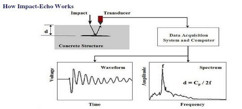
Impact Echo (IE) investigations are performed to access the condition of slabs, beams, walls, pavements, runways, tunnels and dams. In its simplest form it is used for measuring the thickness of elements.
Technology
The impact is a short-duration mechanical tap, produced by tapping a small steel sphere or solenoid (in the case of the Olson test-head) against a concrete or masonry Surface. This produces low-frequency stress waves that propagate into the structure and are reflected by flaws and/or external surfaces.
Multiple reflections of these waves within the structure excite local modes of vibration, and the resulting surface displacements are recorded by a transducer located adjacent to the impact. The IE time traces are transformed to the frequency domain via FFT for calculations of the transfer and coherence functions, and the auto power spectrum of the receiver. Spectrum data are used to determine the depth of reflectors according to the following equation:
d = Cp / 2f
Where d is the reflector depth, f is the highest amplitude frequency peak identified in the response, and Cp is the compressional wave velocity (upv or p-wave velocity). Which must be determined via a site based calibration.
Practicalities
The advantage of the IE method over the Ultrasonic Pulse Velocity (UPV) method is that it only one side of the structure needs to be accessible for testing. For IE investigations, relatively smooth, clean surfaces are needed. Water can be applied to the surface to improve coupling of the receiver.
This method is performed in accordance with ASTM C1383-98a. Measurement accuracy is typically at ±2% at high resolution when equipment is calibrated on a known thickness location.
What we offer
Concrete Thickness Gauge (CTG)
NDE 360 with Impact Echo
Freedom Data PC with Impact Echo
Ultrasonic Pulse Echo
Intro
The Ultrasonic Pulse Echo method offers a new technique to examine concrete elements non-destructively from one surface. A mechanical wave (shear wave) is created at the surface and its reflection and its backscatter from the internal structure of the element is analysed. It has several advantages over other techniques:
Only single-sided access is needed
It is highly accurate in determining reflector position and estimating size and shape
Minimal surface preparation is required (dry contact)
Electronic equipment provides instantaneous images
Detailed images can be produced with automated systems
It has other uses, such as flaw detection, depth, cover to bars in steel fibre concrete, location of voids in post tensioning ducts and detection of ungrouted dowels.
Technology
The transducers produces shear waves that propagate into concrete. The transducer then can act as a receiver to listen to waves echoing back from the bottom of the concrete elements or an obstacle within the concrete. The velocity of shear waves and the arrival time are measured to calculate the travelling distance (thickness of concrete elements). The computer builds up a coloured image of the concrete interior using Synthetic Aperture processing. The different colours represent the intensity of the reflected waves. Sources of reflection can be different materials such as air voids (cracks, honeycombing etc) within the concrete.
Practicalities
Only single-sided access is needed when the pulse-echo technique is used and it can work on rough surfaces. Dry contacts between probes and the surface of the concrete elements gives the user a much easier working experience.
The air concrete interface of walls and suspended slabs give a very strong wave reflection as does the interface of the internal wall of a pipe, even when running full. Although the shear wave may have sufficient energy to reflect off the opposite face up to 2m away 0.5m is more typically the limit, and even then if there are defects in the concrete the rear surface may not be seen.
The thickness of a slab on grade will generally be detected as the concrete will be a very different material to the material it is sitting on. However, blinding concrete may give an overestimation of thickness where the interface between it and the structural concrete cannot be seen.
What we offer
MIRA -Ultrasonic Pulse Echo Imaging
Ground Penetrating Radar
Intro
GPR, short for “Ground Penetrating Radar” is an imaging technology used for subsurface earth exploration and investigation. GPR uses electromagnetic wave propagation to image and identify changes in electrical and magnetic properties in the ground. GPR systems are widely used for concrete geometry testing such as locating underground rebar, cable and pipes, etc.
Technology
GPR radiates electromagnetic waves through a concrete surface and receives reflected signals from objects such as reinforcing steel bars, cavities, or other objects that have different electrical characteristics from concrete. Object location and depth are then displayed and recorded as image data. Therefore, GPR systems are used to map the thickness of concrete elements like bridges, tunnels and piles etc.
Practicalities
GPR system doesn’t work on fresh concrete. It is difficult and sometimes impossible to measure the thickness of slabs on ground as solid ground is similar in dielectric properties to concrete and other interference from embedded elements make it hard to return a reliable measurement of concrete thickness. While it is much easier for GPR to assess concrete thickness on a suspended slabs as the reflection from air elements is relatively clear. Ground truthing or “curve fitting” processing from the shapes of a number of hyperbola reflection is required for accurate depth measurement.
What we offer
Handysearch
Conquest SL
Conquest
Tr-HF
Aladdin