
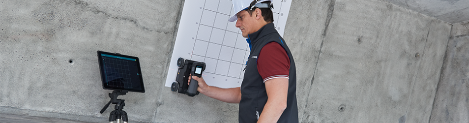
In-Place Inclinometer
Inclined In-place Inclinometers (IPI) are used primarily for monitoring the downstream concrete face of rock filled dams or other inclined applications.
They are installed within inclinometer casing, which is either placed in a borehole, concreted in or attached to a structure. They consist of a series of wheeled sensors placed at various depths within the casing which are connected together with extension rods. Each sensor has specially designed connectors which allow them to move independently.
They consist of a series of wheeled inclinometer probes which contain one or two MEMS sensors and are placed at various depths within the casing and connected together with extension rods. The electrical BUS connection between each sensor is routed internally through the extension rod ensuring water-tightness and eliminating external connectors which are prone to leak and damage. This unique cable-free joint design ensures quick and easy watertight connection.
The design allows each sensor to move independently to each other without influence from the sensors above or below. This provides a profile of displacement over the complete length of the installation. The extension rod lengths can be varied to suit individual gauge length requirements and sensors can also be concentrated in areas where movement is expected.
In-place Inclinometers are typically used and designed for safety critical applications where ‘real time’ monitoring and early warning is required in order to protect life and valuable assets. They are easy to automate using data acquisition systems, WI-SOS 480 wireless communication and the data can be visualised using the GeoAxiom Vista software.
There are three different kinds of in-place inclinometer:
- Inclined
- Vertical
- Horizontal


Inclined Vertical Horizontal
System Components
-

Top Hangar
Used to suspend the complete string. Placed on the top of the 70mm inclinometer casing. Weight 0.3kg -

Wire Hangar Extension
A 3mm wire suspension rope used to position the first sensor at the required depth and is connected to the top collar hanger and the IPI top fly lead assembly. Available either as pre-assembled lengths (1, 2, 3, 4m) or supplied as site adjustable. Weight 0.05kg/m -

IPI Top Fly Lead Assembly
A universal component which acts as top suspension adaptor and cable connector. Fitted as standard with 4.5m of digital BUS cable for connection to a readout or data logger. Other cable lengths available on request. Weight 0.5kg -

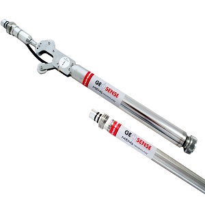
In-Place Inclinometer Probe
Instrument fitted with two (Biaxial) MEMS sensors. It is mounted within a watertight stainless steel tube fitted with two wheel sets that run in the internal grooves of inclinometer casing. One set has a fixed wheel and the other is sprung loaded. The output from the sensors is digital RS-485 BUS so that several IPIs can be connected together on one single cable. Weight 1.3kg -

Extension Rod
Used to connect each IPI sensor together to create a full tilt profile. Specially designed quick connecting fittings on each end, together with anintegral internal signal cable. Available in 0.5, 1, 1.5, 2, 2.5m lengths. (Special lengths are available on request). Weights: 0.5m - 0.75kg; 1m - 1kg; 1.5m - 1.45kg; 2m - 1.9kg; 2.5m - 2.35kg -
Extension Rod with Settlement Sensors [IPI-X only]
Extension Rod with internal Positional Sensor to create a full settlement profile. -
![Magnetic Target [IPI-X only]](/images/Instrumentation/Inclinometers/IPI-X-6-Magnetic-Target.png)
Magnetic Target [IPI-X only]
Attached to the outside of the casing to measure vertical displacement. -

Bottom Wheel / Termination
Fitted with a rigid joint, the bottom wheel assembly acts as the base reference from which all other readings are taken. It is fitted with an integral end termination resistor which is required at the end of the RS-485 string. Fitted with an eye bolt for support rope. Weight 0.5kg.
Features
- Quick & easy to install
- Uni-axial and bi-axial options
- MEMS sensors
- In-built temperature compensation
- Single cable digital BUS system
- Stainless steel construction
- Waterproof tested to 20 bar
- Removable
- Variable gauge length
- High accuracy and precision
- Fully EMC tested
Applications
- Retaining/diaphragm walls
- Dams
- Slope stability
- Tunnelling
- Slope stability
Specifications
Models
| Orientation | Range | Uniaxial | Biaxial |
| Vertical | ±15° from vertical | IPI-V-1 | IPI-V-2 |
| Inclined | ±15° from 45° | IPI-I-1 | IPI-I-2 |
| Horizontal | ±15° from horizontal | IPI-H-1 |
Performance
| Accuracy | ±0.004° (±13.5 arc sec, ±0.07 mm/m) ±0.0125% FS |
| Resolution | 0.0005° (2 arc sec, 0.01 mm/m) 0.0017% FS |
| Repeatability | ±0.002° (±7.2 arc sec, ± 0.037 mm/m) ±0.007% FS |
| Temperature Sensor Range | 40 to +85 °C |
| Temperature Sensor Accuracy | ±1 °C |
| Operating Temperature | -40 to +85 °C |
| Thermal Stability | ±0.005% FS/°C |
Electrical
| Sensor Type | Biaxial MEMS |
| Output Signal | RS-485 digital BUS |
| Output Unit | Sine of angle, degrees |
| Supply Input | 8-15 V DC |
Physical
| Sensor Diamater | 25 mm |
| Sensor Weights | 0.9, 1.3, 1.8, 2.3, 2.7, 3.2 kg |
| Sensor Gauge Lengths | 0.5, 1, 1.5, 2, 2.5, 3 m |
| Compatible Casing Sizes | |
| Enclosure Rating | IP68 (20 bar) |
Materials
| IPI Probe | 316 Stainless Steel |
| Extension Rods | ± 1mm/30m |
| Wheels | Heat-treated 17/4 stainless steel |
| O-rings | Viton® |
Extension Cable
| Construction | 2 x twisted pair, braided, PUR sheath |
| Type | Type 800 - multi-core with braid |
| Diameter | 8 mm |