
Profometer Corrosion PM8500
Half Cell Potential Meter
 Screening Eagle Technologies have expanded their concrete portfolio with an advanced digital-first solution to one of the biggest challenges of the built world today – corrosion.
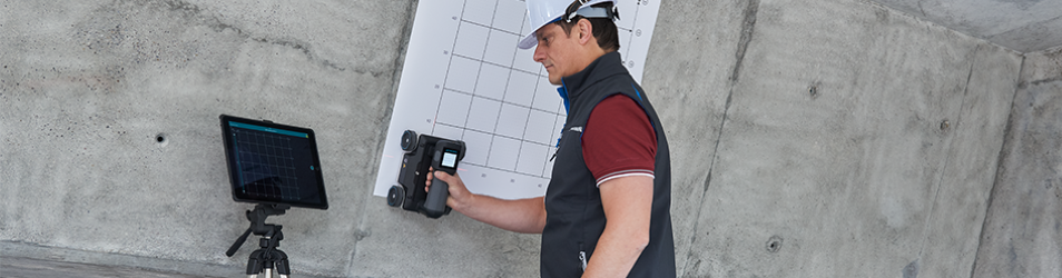
The new PM8500 is the most complete half-cell solution for rapid onsite mapping of corrosion potential in reinforced concrete. The light and wireless design with unique wheel electrodes enables the world’s fastest data acquisition with real-time data visualization and analytics.
The state-of-the-art sensor comes with the powerful Profometer app software with a flexible, customizable grid, capable of handling up to 10’000 square meters scan capacity. Together, the sensor and software make the PM8500 an effective solution for any type of corrosion inspection on concrete structures such as underground parking columns, walls, slabs or bridge decks.
The half-cell method is used to identify active corrosion of rebars based on the electro chemical properties of reinforced concrete. All the Proceq electrodes (rod or wheel) are based on a Copper/Copper Sulphate (Cu/CuSO4) half-cell.
This is why the PM8500 voltage input range allows also the connection of Silver/Silver Chloride (Ag/AgCl) electrodes or Saturated Calomel (Hg/Hg2Cl2) reference electrode. The standard cable supplied may be connected to most third party rod electrodes.
Software Integration
 Data is collected in the Profometer app for iPad, the very same application used for the Profometer PM8000 Cover Meter and rebar locator.
From there data is syncronised with Workspace, the cloud data storage system for all Proceq / Screening Eagle Technologies test systems.
For users who need to integrate Potential Mapping with other investigations, such as visual inspection, cover measurement, and laboratory reports, the latest version of Screening Eagle INSPECT will store PM8500 sensor data and allow for visualisation to be overlayed on 2D view maps of a structure.
Test Method
 Electrical potentials are the most common technique used for assessment of the extent of reinforcement corrosion. A copper sulphate half cell held against the concrete surface can be considered as a battery with one side of the battery being the copper rod in the copper sulphate solution (called a ‘reference half cell’) and the other side the steel bar in concrete.
The potential difference (voltage difference) is measured by a voltmeter connected to the rebar and copper rod. The reference half cell is moved from point to point on the concrete surface. As the potential of the copper rod in coper sulphate solution is constant the different voltages measured are the difference in potential created by differences in potentials at the bar surfaces.
However the measurements are not the actual bar potentials, only a reflection of them. The measured values are affected by the resistivity of the concrete, the cover and various other factors.
The electrical potential distribution over a corroding area can be represented as a “funnel” centred on the anode, whose shape and extent is defined by the actual ongoing corrosion as well as by the concrete electrical resistivity.
System Features
Measurement Modes
 Basic Mode
- Expert Mode
- Spot Scan (rod electrode)
- Line Scan (wheel electrode)
- Area Scan (wheel electrode)
- Fixed Grid (rod electrode)
- Flexible and Variable Grid (Wheel electrodes)
Review Modes
- Potential View
- Displays a heat map with the potential values
- Statistic View
- Distribution and cumulative distribution graph
- Chipping Graph View
- Displays the corroding areas based on chosen threhsolds
Reference Electrode Configurations
 The detection of the regions where active corrosion begins involves the measuring of the localized negative values of the half-cell potential (i.e. corrosion potential).
When using a rod electrode the user has to define a grid fine enough not to miss any local negative peak, while the use of a wheel electrode on the PM8500 ensures a new level of accuracy.
The wheel system is fast enough to measure the electrical potential continuously along its linear paths, ensuring the most negative measured value will always be recognized and stored with its associated location.
Technical Specifications
| Technology | Half Cell Potential Mapping |
| Measurement Units | Corrosion potential in millivolts (mV) |
| Connectivity | Wireless - Bluetooth |
| Influence Depth | First rebar layer |
| Measurement Range | -3000 mV to +3000 mV |
| Resolution | ± 1 mV |