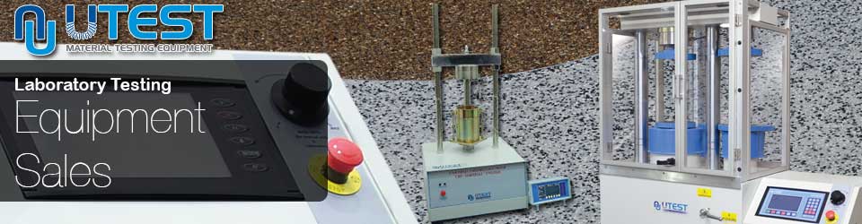
Soil - Triaxial Test Systems
It is very important to establish the mechanical properties of soils when designing foundations, embankments and other soil structures. Building constructions, excavations, tunneling and similar applications have several effects on the subsoil structures. These effects are successfully simulated with Triaxial Tests where the stress-strain relation of undisturbed soil specimen is investigated by subjecting the soil sample to different stress levels and drainage conditions.
The UTEST Triaxial Test System provides automated triaxial compression tests on cylindrical undisturbed and remoulded soil samples. Unconsolidated undrained (UU), consolidated drained (CD) and consolidated undrained (CU) compression tests can be automatically run, controlled and reported using this apparatus.
Unconsolidated Undrained (UU) Test
 For the UU test, the specimens, which should be saturated before the test, are exposed to a confining fluid pressure in a triaxial chamber. Once the specimen is inside the triaxial cell, the cell pressure is increased to a predetermined value by rotating the knob, and the specimen is brought to failure by increasing the vertical stress by applying a constant rate of axial strain. Saturation and consolidation are not permitted to keep the original structure and water content of sample untouched. The results can only be interpreted in terms of total stress, as pore pressures are not measured during the test. These tests are usually performed on three specimens of the same sample, subjected to different confining stresses.
Since all specimens are supposedly saturated, the shear strength are similar for all tests. The results of the test are plotted as curves of principal stress difference against strain. For conditions of maximum principal stress difference (taken as failure) Mohr circles are plotted in terms of total stress. The average undrained shear strength should be noted, and the failure envelope drawn tangential to the Mohr circles in order to find the "undrained cohesion intercept" and undrained "angle of shearing resistance".
Consolidated Undrained (CU) Test & Consolidated Drained (CD) Test
 Peak effective strength parameters (c' and φ') may be determined either from the results of consolidated undrained (CU) triaxial compression tests with pore pressure measurement, or from consolidated drained (CD) triaxial compression tests. The consolidated undrained/drained triaxial compression tests are generally conducted in several stages, which concern the successive saturation, consolidation and shearing of each of the three specimens.
To ensure that the pore fluid in the specimen does not contain free air, it must be undergo saturation before any other testing can occur. Saturation is generally achieved by leaving the specimens to swell against an elevated back pressure. Back pressure (which is simply an imposed pore pressure) is administered through a volume change gauge to the top of the specimen, while a cell pressure of slightly higher value is also applied. To allow time for equalization at each stage, both the cell pressure and back pressure generally increase in increments. The degree of saturation can be expressed in terms of Skempton's pore pressure parameter (Skempton, 1954):
Δ u
B=__________
Δ σ3
where Δu is equal to change in pore pressure for an applied cell pressure change of Δ σ3. For an ideally saturated soil, B is equal to unity. Before the specimen can be considered as fully saturated and the consolidation stage started, it is recommended by several standard test methods that a value of B greater than, or equal to, 0.95 must be attained. The consolidation stage of an effective stress triaxial test is performed for two reasons. First, three specimens are tested and consolidated at three different effective pressures, in order to give specimens of different strengths which will produce widely spaced effective stress Mohr circles. Secondly, the results of consolidation are used to establish the minimum time to failure in the shear stage. The effective consolidation pressures (i.e. cell pressure minus back pressure) will normally be increased by a factor of two between each specimen, with the middle pressure approximating to the vertical effective stress in the ground. When the consolidation cell pressure and back pressure are applied to the specimen, readings of volume change are made using a volume change device in the back pressure line. Pore pressure is measured at the specimen base, with drainage to the back pressure line taking place through a porous stone covering the top of the specimen. The coefficient of consolidation of the clay can be determined by plotting volume change as a function of the square root of time. Theoretical considerations indicate that the first 50% of volume loss during consolidation should show as a straight line on this plot. This straight line is extended down to cut the horizontal line representing 100% consolidation, and the time intercept at this point (termed "t" by Bishop and Henkel) 100 can be used to obtain the coefficient of consolidation.
Consolidated Undrained (CU) Test
Once consolidation has been performed, the specimen is to be isolated from the back pressure. Once this has occurred, the rate of vertical movement of the compression machine platen must be set according to the outcome of the consolidation. During the shear stage, the vertical stress is increased by the loading ram, and measurements are made at regular intervals of deformation, ram load and pore pressure. These intervals are converted to graphs of principal stress difference (σ1- σ3) and pore pressure as a function of strain, and failure is normally taken as the point of maximum principal stress difference. The effective stress Mohr circles are plotted for the failure conditions of the three specimens which has been subjected to different consolidation level, and the gradient and intercept of a straight line drawn tangential to these circles defines the effective strength parameters c' and φ'.
Consolidated Drained (CD) Test
The consolidated drained triaxial compression test which includes volume change measurement during shear is carried out in a similar progression to the consolidated undrained test. However the difference between the two is that during shear, the back pressure stays connected to the specimen which is loaded sufficiently slowly to refrain from the development of excess pore pressures. Users can expect the shear stage of a drained triaxial test to take up to 7 to 15 times longer than the shear stage of an undrained test with pore pressure management. Once shearing is complete, the results are presented as graphs of principal stress difference and volume change as a function of strain, and the failure Mohr circles are plotted to give the drained failure envelope defined by the parameters cd' and φd'. Triaxial CD-CU-UU equipment is computer controlled. Once test values have been transferred to a computer, the data processing can be completed with Triaxial software on a Windows operating system. All data is compatible with Excel programs. The load data and axial displacement data are transferred and recorded through BC 100 Unit to the software. Cell pressure, back pressure and pore pressure from triaxial cell and volume change data are transferred and recorded through the Unilogger to the software.
| Typical configuration of system for different tests (UU-CU-CD) | |||
| Products Code | Description | UU | UU-CU-CD |
| UTM-0108.SMPR | Multiplex Universal Electromechanic Test Machine | 1 | 1 |
| UTGM-1180 | Load Cell 5kN | 1 | 1 |
| UTS-2400 | Triaxial Cell | 1 | 1 |
| UTS-2405 | Block with One Connection Line for Triaxial Test Cells | 1 | - |
| UTS-0406 | Block with Three Connection Line for Triaxial Test Cells | - | 1 |
| UTGM-1420 | Pressure Transducer | 1 | 3 |
| UTS-2408 | Oil an Water Constant Pressure System | 1 | 2 |
| UTS-2415 | Automatic Volume Change Unit | - | 1 |
| UTG-0320 | Static Unilogger (4 Channels) | - | 1 |
| USOFT-2419 | Software to Perform UU Triaxial Tests | 1 | - |
| USOFT-2420 | Software to Perform CU-CD Triaxial Tests | - | 1 |
| UTS-1330 and UTGP-1140 | De-Airing Water Tank (7L) and Hose | 1 | 1 |
Multiplex Universal Electromechanic Test Machine
 The UTM-0108.SMPR Multiplex Universal Electromechanic Test Machine is a Servo Controlled Multiplex Machine supplied complete with UTGM-1210 50 kN Load Cell, UTGM-0062 25 mm Linear Potentiometric Transducer and UTC-4930.FPR BC 100 Data Acquisition and Control Unit. 5 kN Load cell should be ordered separately for Triaxial Tests.
The Frame capacity is 50 kN. This functional digital loading frame includes a microprocessor controlled drive system with an advanced servo motor which allows the operator to conveniently set any test speed via the membrane keyboard. The keyboard consists of adjustment buttons such as "start", "increase", "automatic", "manual", "down", "up". The testing speed can be set between 0,00001 mm/min to 51mm/min. When the load and displacement is reached to 99% value of the set measuring range, the test will automatically cease.
The BC100 unit collects the load and displacement values and these can then be transferred to PC for further processing with the USOFT-2419 UU and USOFT-2420 CU-CD Software.
| Dimensions | 550 x 650 x 110 mm |
| Weight | 95 kg |
| Power | 750 W |
BC100 unit
BC100 TFT unit is designed to control the machine and processing of data from load-cells, pressure transducers or displacement transducers which are fitted to the machine.
The front panel of the unit consists of an 800x480 pixel 65535 colour-resistive touch screen display and function keys. It also includes 4 analogue channels for load-cells, pressure transducers or displacement transducers. The front panel is where all the operations of the BC100 are controlled.
The menu options on the BC100 are convenient and user-friendly. It displays all menu option listings simultaneously, allowing the operator to access the required option in a seamless manner to activate the option or enter a numeric value to set the test parameters. Real-time "Load vs. Time", "Load vs. Displacement" or "Stress vs. Time" graphics can be drawn with the BC100 digital graphic display.
BC100 unit offers many additional unique features. It's internal memory is capable of holding more than 10,000 test results. The BC100 unit has support for various off-the-shelf USB printers, supporting both inkjet and laser printers (ask for compatible models). Due to its built-in internet protocol suite, every feature of the BC100 unit can be controlled from anywhere around the world.
Main Features
- Can make test with displacement or load control.
- Real time display of test graph.
- CPU card with 32-bit ARM RISC architecture
- One analogue channel for high capacity load cell, one analogue channel for low capacity load cell, one analogue channel for displacement transducer and one analogue channel for cell pressure (only for UU tests)
- Programmable digital gain adjustment for load-cell, pressure transducers, strain-gauge based sensors, potentiometric sensors, voltage and current transmitters
- 1/256000 points resolution per channel
- 10 data per second sample rate for each channel
- Ethernet connecting for computer interface
- 800x480 resolution 65535 colour TFT-LCD industrial touchscreen
- 4 main function keys
- Multi-language support
- 3 different unit system selection; kN, Ton and lbf
- Real-time clock and date
- Test result visualization and memory management interface
- Remote connection through Ethernet
- USB flash disc for importing test results and for firmware
- USB printer support for inkjet and laser printers (ask for compatible models)
- Camera support for real-time video recording during test (ask for compatible models)
- Free of charge PC software for the test control and advanced report generation
Data Acquisition & PC Software
 The CU-CD triaxial test is a complex test that requires:
- Load data
- Displacement data
- 3x pressure data from triaxial cell
- Volume change data
The BC100 unit transfers and records load data and displacement data to the software. 3 pressure data from triaxial cell and volume change data are transferred and recorded through the unilogger to the software.
The UTEST software for CD-CU tests is compatible with UTEST UTG-0320 datalogger and BC 100 unit. UTEST Unilogger can be connected to PC by RS232 port. The user can manually set all channel gains and the accuracy of the reading can be easily increased.
Triaxial Software is a modular software that is useful when a user wants to complete a new test, as it directs the user step by step. First, the software wants to input initial measurements such as diameter, height, sample weight etc. This is the stage where the user decides whether a CU or CD test will be performed and enters the cell pressure increment steps, back pressure differential pressure and effective stress that will be used on consolidation.
Once the initialization stage is complete, the user moves on to the Saturation Cell Pressure increment stage. Cell pressure must be incremented to the pressure entered at initialization stage. During this stage the software calculates B and pore pressure and submits their graph respect to time. This stage must conclude when B value saturates. Generally the value of B would not reach to 0.95, therefore a back pressure increment stage must be completed. Before this stage begins, the software commands what back pressure must be applied, respect to the initial settings. During this stage, the software displays volume change and pore pressure data.
Saturation stages can be done recursively at most of 10 cycles. For further investigation and report facilities, the relevant data of each stage is written to respective files. When the saturation is completed, the consolidation stage can be implemented. During this stage, the software commands to adjust both cell and back pressure to apply effective stress. During the consolidation stage, volume change, pore pressure and pore pressure dissipation percent is drawn as graphs. Once this stage is complete, the shear stage of CU or CD will begin. Using the results found in the consolidation stage, the software proposes the shear speed for this stage. Before shearing begins, axial displacement and force must be tared.
During the shear stage, deviator stress, pore pressure, ơ' versus ơ'3 and s' versus t' graphs are drawn. 4 different test specimens can be configured in the same file. All the results are used for drawing Mohr circles. The data is assessed with respect to specimen shear end condition. This condition can be selected as constant pore pressure, constant volume change effective prime deviator ratio etc. With the final measurements, one set of data is closed.
The raw data can be exported to Microsoft Excel. Without using Microsoft Excel environment all reports can be printout which includes summary of each stage with relevant graphs.
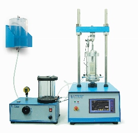
Triaxial Cells & Sample Preparation
 UTS-2400 Standard Triaxial cell for 38 and 50 mm dia. samples
UTS-2401 Standard Triaxial cell for 70 and 100 mm dia. samples
Corrosion is minimized due to the design of the cell. Particular attention has been paid to the quality of finish between the piston and the head. An O-ring seal is fitted and a special lubricant is applied to reduce friction to a minimum and eliminate water leakage. The piston load capacity is designed to accept high axial loads which may be present during the final stages of a test.
Each cell has five take-off positions drilled in the base for top drainage/back pressure, pore water pressure and bottom drainage. Each cell is supplied complete with three volume change valves and an anvil for displacement transducer. The cells are compatible with a range of base adapters and various accessories for successful testing of a wide range of specimens.
The cell capacity is designed to tolerate confining pressures as high as 1700 kPa which is enough for simulating most in-situ conditions.
UTS-2400 UTS-0401 Dimensions 160 x 160 x 400 mm 210 x 210 x 550 mm Weight 4.5 kg 12 kg
| UTS-2400 | UTS-0401 | |
| Dimensions | 160 x 160 x 400 mm | 210 x 210 x 550 mm |
| Weight | 4.5 kg | 12 kg |
Cell Accessories
| Sample Diameter (mm) | 38 | 50 | 70 | 100 | UU Test | CU-CD Test |
| Base Adaptor | UTS-0420 | UTS-0450 | UTS-0470 | UTS-0500 | YES | YES |
| Porous Top Cap | UTS-0421 | UTS-0451 | UTS-0471 | UTS-0501 | YES | YES |
| Nylon Tubing for Drainage | UTS-0422 | UTS-0452 | UTS-0472 | UTS-0502 | - | YES |
| Pair of Porous Discs | UTS-0423 | UTS-0453 | UTS-0473 | UTS-0503 | - | YES |
| Rubber Membrane | UTS-0424 | UTS-0454 | UTS-0474 | UTS-0504 | YES | YES |
| Membrane Placing Tool (Stretcher) | UTS-0425 | UTS-0455 | UTS-0475 | UTS-0505 | YES | YES |
| O Rings (10 pcs) | UTS-0426 | UTS-0456 | UTS-0476 | UTS-0506 | YES | YES |
| O Ring Placing Tool | UTS-0427 | UTS-0457 | UTS-0477 | UTS-0507 | YES | YES |
| Lateral Filter Paper (50pcs) | UTS-0428 | UTS-0458 | UTS-0478 | UTS-0508 | - | YES |
| Filter Paper Discs (100 pcs) | UTS-0429 | UTS-0459 | UTS-0479 | UTS-0509 | - | YES |
| Plastic Discs (2 pcs) | UTS-0430 | UTS-0460 | UTS-0480 | UTS-0510 | YES | - |
Sample Preparation Accessories
| Sample Diameter (mm) | 38 | 50 | 70 | 100 |
| Split Sand Former | UTS-0431 | UTS-0461 | UTS-0481 | UTS-0511 |
| Split Mould | UTS-0432 | UTS-0462 | UTS-0482 | UTS-0512 |
| Cutter | UTS-0436 | UTS-0466 | UTS-0486 | UTS-0516 |
| Aluminium Dolly | UTS-0437 | UTS-0467 | UTS-0487 | UTS-0517 |
Oil and Water Constant Pressure System
 UTS-2408 Oil and Water Constant Pressure Unit, 1700 kPa220-240V, 50-60Hz, 1ph
UTS-0409 Digital Pressure Gauge, 1700 kPa (250 psi)
UTGM-1420 Pressure Transducer, 2000 kPa
The Oil and Water Constant Pressure Unit is extremely versatile and can be used collectively with a wide range of test equipment. The unit provides continuous variable pressure up to 1700 kPa. Pressure can be easily increased or decreased by turning the control wheel.
The Unit is designed for providing cell/back pressure in triaxial tests. For customers who have appropriate pressure monitoring equipment, the apparatus is supplied without a gauge.
As optional equipment for monitoring the pressure of the unit;
- The Digital Pressure Gauge (UTS-0409) or
- The pressure transducer(UTGM-1420) which can be used with UTEST BC100 TFT Unit on the Multiplex Universal Electromechanic Test Machine (UTM-0108) for only UU test or
- The pressure transducer(UTGM-1420) which should be used with the datalogger (UTG-0320) for CU-CD tests can be used and preferred optional equipment should be ordered separately.
The machine includes a clear hydraulic/water interface reservoir and up to 1 litre capacity of water is available under pressure. Supplied complete with 2 litres of No.46 regular hydraulic oil.
| Product Code | Dimensions | Weight | Power |
| UTS-2408 | 300 x 250 x 250 mm | 7.5 kg | 35 W |
| UTS-0409 | 150 x 150 x 100 mm | 0.6 kg |
Volume Change Measurement
UTS-2415 Automatic Volume Change Unit
To ensure linear movement of the piston is exactly proportional to the volume of water in the calibration chamber, the Unit includes a piston connected to a 25 mm travel linear transducer which is sealed against a precision machined calibration chamber.
The apparatus creates an electrical signal proportional to the volume of water flowing through the unit. By connecting it to the data acquisition system the measured volume change will be used by software during the test and in final report.
Capacity : 100 cm3
Transducer Input : up to 12 V DC
Accuracy : ± 0.1 ml
| Dimensions | 260 x 260 x 400 mm |
| Weight | 5 kg |
Pressure Transducer and Connection Block for Pore Water Pressure Measurement and De-Airing
UTGM-1420 Pressure Transducer, 2000 kPa
UTS-2405 Block with One Connection Line for Triaxial Test
UTS-0406 Block with Three Connection Lines for Triaxial Test
The Pressure Transducer is used for the measurement of cell or back or pore pressure of water in triaxial test systems and also should be used with an UTEST BC100 TFT Unit (UTC-4930) or a datalogger (UTG-0320)
The Block for triaxial test cells is used for connection of the pressure transducers and de-airing in the water hoses.
De-Airing Water
UTS-2418 De-Airing Water Apparatus, 230V, 50Hz, 1ph
UTS-1330 De-Airing Water Tank, 7 L.
UTGE-3580 Vacuum Control and Water Connection Panel with Regulator and Vacuum Gauge Manometer
UTGE-3585 Connection Panel for Vacuum and Water with Vacuum Gauge Manometer
UTGE-3505 Vacuum Pump 51 L/min. Capacity,220-240 V 50-60 Hz
UTGG-2015 Filter Flask 2000 ml
UTGE-3570 Air Drying Unit / Water Trap, Vacuum Type
UTGP-1140 Plastic Hose, Ø8mm, 6m
The UTS-2418 De-Airing Water Apparatus is a compact and self-contained equipment which can de-air water quickly and efficiently down to levels of dissolved oxygen acceptable for geotechnical test methods. The apparatus used in conjunction with the de-airing tank (UTS-1330). A vacuum system allows air to be removed from the water. De-airing tank should be ordered separately.
The first option for de-airing water;
- De-Airing Water Apparatus UTS-2418
- De-Airing Water Tank(UTS-1330)
- Vacuum Control and Water Connection Panel with Regulator and Vacuum Gauge Manometer(UTGE-3580) or Connection Panel for Vacuum and Water with Vacuum Gauge(UTGE-3585) (These panels are optional)
- Plastic Hose (UTGP-1140)
The second option for de-airing water;
- Vacuum Pump (UTGE-3505),
- Filter Flask (UTGG-2015) or Air Drying Unit / Water Trap (UTGE-3570)
- De-Airing Water Tank (UTS-1330)
- Vacuum Control and Water Connection Panel with Regulator and Vacuum Gauge Manometer (UTGE-3580) or Connection Panel for Vacuum and Water with Vacuum Gauge(UTGE-3585) (These panels are optional)
- Plastic Hose (UTGP-1140)
By using UTGE-3580 Vacuum Control and Water Connection Panel, vacuum pressure degree can be regulated.
By using UTGE-3585 Connection Panel for Vacuum and Water with Vacuum Gauge Manometer and UTGE-3580 Vacuum Control and Water Connection Panel with Regulator, de-airing water equipment can be used without repeated assembling the hoses.
| Product Code | Dimensions | Weight |
| UTS-2418 | 465 x 240 x 340 mm | 15 kg |
| UTGE-3580 | 450 x 150 x 500 mm | 7 kg |
| UTS-01330 | 250 x 250 x 250 mm | 2.7 kg |
| UTG-1442 | 120 x 220 x 220 mm | 0.5 kg |
| UTGE-3505 | 300 x 150 x 240 mm | 8.5 kg |
| UTGE-3570 | 70 x 80 x 170 mm | 0.5kg |