
Spectral Analysis of Surface Waves (SASW)

SASW tests allow the user to determine the different profiles in pavement layers or soil layers, including the depth, velocity and also the condition of each of these layers. This allows for common applications such as thickness measurement of pavement systems, confirming open crack depths, or the success of crack / join filling with epoxy.
It is all done non-destructively from the top surface of the pavement. The test can be performed on concrete, asphalt, masonry, soil and wood and can be used to investigate profiles up to 90 meters deep.
Applications
Surface wave analysis can determine:
- Road layer or pavement system profiles including the surface layer, base and sub grade materials.
- Determination of soil profiles including soil velocites needed for earthquake and dynamic loading analysis
- Determination of abutment depths of bridges
- The condition assessments of concrete liners in tunnels, and other structural concrete conditions
- Crack depth in monolithic concrete
How it works
 Surface wave testing uses the dispersive characteristics of surface waves to determine the variation of the shear wave velocity (stiffness) of layered systems with depth. The SASW testing is applied from the surface which makes the method non-destructive and non-intrusive. In SASW tests, two receivers are placed on the surface, and a hammer is used to generate the wave energy. An Olson Instruments' Freedom Data PC or NDE 360 records the hammer input and the receiver output.
Access
The SASW method a flat surface to place sensor on. The width between impct and each sensor limits the investigation depth, deeper investigation requires a longer span.
As a rule of thumb, if one is interested in material properties to a certain depth, the reciever spacing should be one and a half or twice that depth.
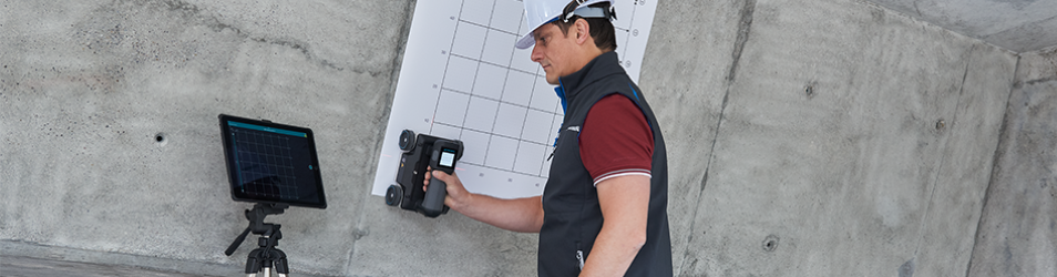
Setup Arrangement
This image shows the general field arrangement used in SASW testing. Receiver spacings ranging from 15 cm to more than 90 m have been used in the field to investigate depths from 5 cm to greater than 90 m.

Collection of Data
In SASW tests, two receivers are placed on the surface, and a hammer is used to generate the wave energy. Short receiver (typically accelerometers) spacings are used to sample the shallow layers while long receiver (typically velocity transducers) spacings are used in sampling for deep materials.
Two profiles, a forward profile and a reverse profile, are typically obtained in SASW measurements where the accessible surface is struck by a hammer on two opposite sides of the receivers. A signal analyser is used to collect and transform the receiver outputs to the frequency domain. Two functions in the frequency domain are of great importance in SASW tests:
- The cross power spectrum between the two receivers (used in the preparation of the experimental dispersion curve)
- The coherence function (used to ensure that high signal to-noise ratio data is being collected).
Accuracy

SASW measurements are accurate to within 5% for the determination of the thickness and stiffness of the top layer during pavement layer analysis or of the concrete liner of a tunnel.
Correlation between SASW and Crosshole Seismic tests on soil sites showed that the values from both tests typically compare within a 10% difference.
Case Study
The figure right shows dispersion curves determined from SASW measurements on asphalt pavement. Shown in this figure is the variation of the surface wave velocity (modulus) as the asphalt layer warms up. The SASW measurements were also effective in determining the thickness of the surface layer.
Platforms Available

We offer two devices available for the SASW technique. These include the NDE 360 and Freedom Data PC. These offer differing levels of mobility and on-site analysis. Please see the individual webpages for more in depth specifications for the platforms.