
NDE 360 - The Multi-functional NDE Platform
 Acoustic testing techniques can be used for the investigation of concrete, rock and soil elements above or below ground, and offer engineers or technicians powerful tools with which to assess parameters such as: the thickness of a slab or sub-base, length of a pile, location of construction defects such as voids and cracks, slab support or even detailed geotechnical investigation.
Many techniques have been developed in the last 20 years (i.e. Impact Echo, Impulse Response etc) but the technology was either prohibitively priced or far too cumbersome to use practically. The NDE 360 testing platform addresses these issues by separating the test paraphernalia from processing, now one system can support up to 9 testing methods in a robust, ruggedized, battery powered system giving the mobility and simplicity an engineer in the field needs. Tests can be taken and analysed on site with minimal fuss or data taken back for detailed analysis at the office using robust software while the NDE 360 package keeps working on a different site supporting a different test.
Testing Packages
The NDE 360 system is purchased with one or more testing packages. You can upgrade your NDE 360 at anytime with the purchase of a new add-on. Please see the below for full description of the test packages and their applications.
Pavement, Structural and Tunnel Systems
 ASTM C1383
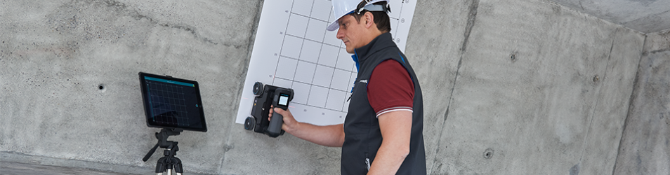
Determine the thickness of a concrete or masonry element and detect internal flaws and for QA of repairs from sound wave resonant echoes. IE Test Head with displacement transducer and solenoid taps the concrete creating a sound-wave. Optional 0.1 kg impulse hammer and accelerometer. Access to only one side of the concrete (or masonry) element is required.
 Roll on smooth concrete for IE scanning of thickness/flaws every 25 mm and scan lengths of up to 4 to 5 m in length. Diagnose voided post-tensioned bridge ducts, void/honeycomb, cracking, delaminations and thickness profiling by scanning. One-sided scans for smoother finish or formed concrete up to 1 m thick.
ACI 228.2
 Used for finding and mapping voids below slabs on grade, dam spillways and behind tunnel liners. Also used on concrete structures for defects. The slab surface is struck with a calibrated impulse hammer and the response collected by an adjacent receiver. Access to only one side of the concrete element is required.
Ultrasonic Pulse Velocity (UPV)
ASTM C597
 Determine the relative strength and quality of concrete and is also used for Locating internal defects. Sonic Pulse Velocity (SPV) for thicker materials. Transmitting and receiving transducers send and receive ultrasonic pulses through concrete, allowing velocity and amplitude to be calculated. Normally requires 2-sided access or access around corners. Test concrete, masonry, wood and stone with UPV and SPV options.
 ACI 228.2
Concrete quality vs. depth (for fire and freeze-thaw damage assessment), and condition assessment of concrete slabs and tunnel liners. Surface waves are created by a hammer strike and collected by two receivers which are in-line at a set spacing. Typically done with the SASW bar as shown. Access to only one side of the concrete element is required. Also conduct SASW tests on masonry and stone.
Multiple Impact Surface Waves (MISW)
 Determine pavement thicknesses of asphalt or concrete, base, subgrade and layer elastic moduli. Structural/tunnel applications. Accelerometer/Geophone receiver(s) measure compression and surface wave arrivals from manual/automated impacts at multiple points. Modeling software for layered systems. One-sided access requirement for asphalt, concrete, masonry, soil and rock.
 ASTM C215/C266
Conduct resonance tests of concrete cylinders/beams or rock cores. Measure Young’s and Shear Moduli of concrete and stone/rock and test concrete for freezethaw durability. Square cast or cut specimens are required for testing per the ASTM standard.
Foundation Depth and Integrity Systems
Sonic Echo/Impulse Response - Pile Integrity Test
 ASTM D5882
SE/IR tests are performed to evaluate the integrity and determine the length
of deep foundations. The foundation top is struck by a hammer and the response of the foundation is monitored by an accelerometer and/or geophone receiver. Either the top or access to the upper side are required for foundation testing.
 ACI 228.2
Used to determine lengths of deep foundations which are long and slender, have inaccessible tops, or have unusual construction (multiple subgrade elements). The structure/foundation is struck by a hammer and the response of the foundation is monitored by a hydrophone or geophone receiver lowered down a cased borehole. A 50-100 mm ø cased borehole is drilled to 3-5 m below the foundation.
-NDT-Equipment.jpg) US investigations can evaluate the integrity and find the length of foundations such as drilled shafts, piers and driven or auger-cast piles. The foundation top is struck by a hammer and the response of the foundation is monitored by a 3-component receiver at multiple vertical locations. A least 1.5-1.8 m of the side of the structural element is required to be exposed for mounting the receiver.
US investigations can evaluate the integrity and find the length of foundations such as drilled shafts, piers and driven or auger-cast piles. The foundation top is struck by a hammer and the response of the foundation is monitored by a 3-component receiver at multiple vertical locations. A least 1.5-1.8 m of the side of the structural element is required to be exposed for mounting the receiver.
Geophysical Seismic Surface Wave Systems
Surface Wave Testing & Multiple Impact Surface Waves (SASW-G, MISW-G)
 Applied primarily to assess seismic velocity and layer thickness of soil and rock for seismic design with SASW or MISW. Surface waves are created by a hammer strike and collected by geophone receivers that are mounted on the soil/rock in a line. Theoretical modeling is used to get soil/rock layer thicknesses and seismic velocities by matching the experimental phase data. Requires access to surface. A linear area of at least 1.5 x the depth in question is required.
Features
- Multiplex up to 4 Channels
- Handheld/Ruggedized Use
- Colour Touch Screen
- Backlit Screen
- 8+ Hours Battery Life
- 1 Gigabyte Removable Compact Flash
- Test, Accept, Reject Key Buttons
- Windows-Based WINTFS Analysis Software
Specifications
- 16 Bit A-D Converters for 4 Channels
- Up to 2 Microseconds, Simultaneous Sampling Rate on Two Channels
- Maximum Nyquist Frequency 250 KHz
- Steps x1, x10, x100, x1000, Selectable per Channel
Software for Tomographic Velocity Imaging
Images of voids, honeycomb, cracks,uncured or weak concrete in beams, columns, and piers using UPV/SPV measurements. Velocities collected using the NDE 360 are fed into the tomography software allowing for 2-D and 3-D displays of the internal make-up of concrete elements. Access to 2 or more sides of the element are required to produce 2D/3D images.